Acoustic archtop modification - adding a pickup
In this post I'm documenting my addition of an electric pickup to an old (50's era) acoustic archtop guitar. You don't see a lot of acoustic archtops these days. Flat tops are much more popular. Archtops have some characteristics that make them unsuitable for some kinds of acoustic music but they have one advantage: the only difference between an acoustic archtop (often referred to as a "jazz" guitar) and a hollowbody electric guitar is the pickup.
One problem with this pickup is that even though the manufacturer lists it as 3/8" thick the cabling comes out of the back of the pickup (towards the body). This adds to the clearance needed between the strings and the body considerably. Initially the treble strings contacted the pickup when fretted past the 15th fret. Also the pickup was angled such that the treble strings made a much stronger signal than the bass strings, which sounded unbalanced. I was able to cut some of the insulation off of the cable enough to take care of the fretting problem and most of the balancing problem.
The pickup brings out 4 conductors which allow for coil splitting but I found the regular humbucking wiring configuration sounded best.
My buddy routed that out on his router table and you can see it turned out well.
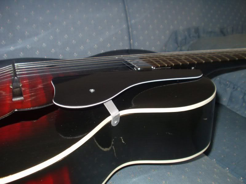
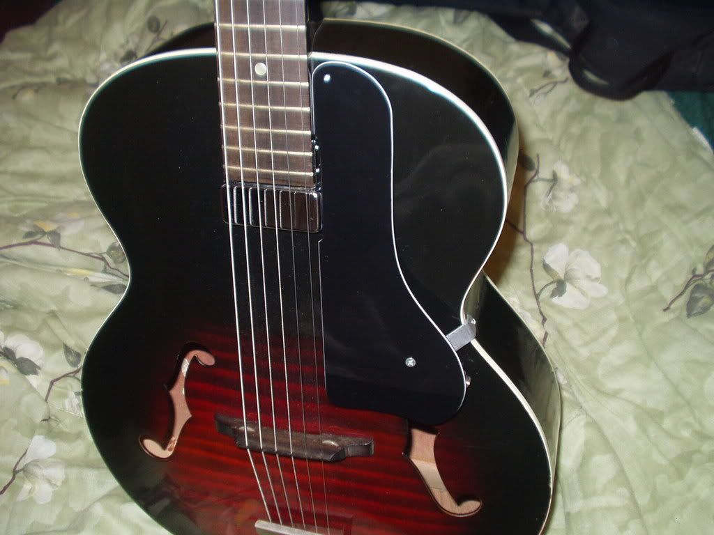
And after the wiring is finished. Note the jack tip on the lower right corner of pickguard.
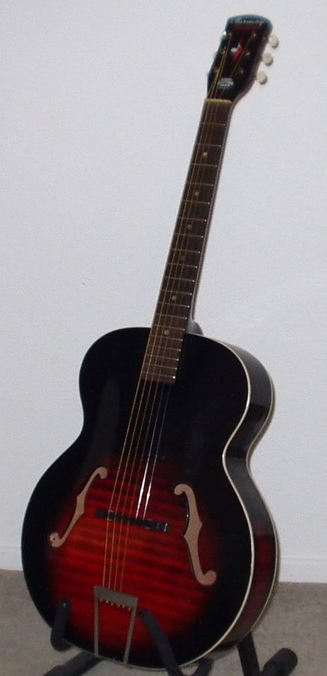
The Guitar
My project guitar is a 1959 Harmony H950 "Monterey Leader" archtop guitar. It's a mid-size archtop with the body made entirely from solid birch. It's not a perfect specimen; if it were I wouldn't want to mess with it. But there's enough dings and scratches that putting some holes in it won't lower the value of the guitar much. I paid $150 for this guitar on ebay.The Pickup
As much of a beater as this instrument is I still don't want to do anything major to it. So cutting a big slot in the top to mount a pickup isn't going to happen. This rules out standard pickups because of the tight clearance between the strings and the top. But a couple companies make humbucker pickups meant to be attached to the fingerboard of an archtop. I found one on ebay for $15.One problem with this pickup is that even though the manufacturer lists it as 3/8" thick the cabling comes out of the back of the pickup (towards the body). This adds to the clearance needed between the strings and the body considerably. Initially the treble strings contacted the pickup when fretted past the 15th fret. Also the pickup was angled such that the treble strings made a much stronger signal than the bass strings, which sounded unbalanced. I was able to cut some of the insulation off of the cable enough to take care of the fretting problem and most of the balancing problem.
The pickup brings out 4 conductors which allow for coil splitting but I found the regular humbucking wiring configuration sounded best.
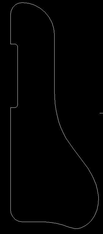
The Pickguard
Next a pickguard was needed to hide the wiring and output jack. My guitar didn't have the original pickguard when I bought it. This is common because the guards were often made from celluloid which deteriorates over time. So I bought some 3-ply plastic from Stew-Mac and drew up a pattern.My buddy routed that out on his router table and you can see it turned out well.
Tone & volume controls
My initial plan was to install tone and volume pots on the pickguard. The only spot with enough clearance for the pots is on the large bulgy area. It seemed like that would get in the way of strumming. I hooked up an external .02uF/500k tone control just to see what kind of difference it would make and it didn't seem to make that much difference. In the end I decided to leave it without controls.Pictures
With the pickup and pickguard mounted.And after the wiring is finished. Note the jack tip on the lower right corner of pickguard.
Sound Samples
These were all played into an Epiphone Valve Jr combo amp and recorded with an inexpensive vocal mic.
posted by Zhyla at 12:36 PM
0 comments
![]()


